
Multi Jet Fusion (MJF) is an additive manufacturing (AM) technology comparable to Selective Laser Sintering (SLS). It is capable of printing highly complex industrial parts and prototypes with a high level of precision and with consistent isotropic mechanical properties.
To help achieve better part quality and dimensional accuracy, it is important that your 3D model closely follows a set of geometric recommendations. This article offers an overview and considerations of the MJF process, best design practices, and weight-saving and cost-reduction design tips and tricks.
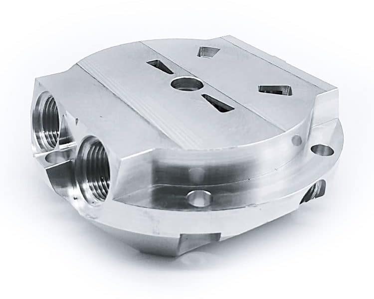
MJF 3D printing design guide
MJF 3D Printing Process
MJF uses an inkjet array similar to that of a color 2D printer to selectively fuse a bed of powdered material (mainly nylon) into a solid layer. The process repeats layer by layer until the final part is complete. Like SLS, MultiJet Fusion belongs to the powder bed fusion 3D printing category; hence, it does not need any support structures, allowing for greater design freedom.
MJF Process Considerations
Shrinkage and Warping: MJF components are susceptible to shrinkage and warping due to the high temperature experienced during printing.
Surface Considerations: MJF prints naturally have rough surfaces. With overly thick designs, there is a higher likelihood that a part will improperly cure and result in an uneven pockmarked surface known as “elephant skin.”
Powder Removal: Excess powder on or inside the part have to be accounted for and cleaned off. Escape holes are needed to remove the unsintered powder from the inner sections of the component.
Characteristics of MJF 3D Printing
Maximum Build Size 380 x 285 x 380mm
Resolution ±0.3mm
Dimensional Accuracy ±0.3% (with a lower limit of ±0.3 mm)
Materials PA11, PA12
Surface Structure Rough
Support Not required
MJF Design Guidelines
Wall Thickness
MJF walls that are designed too thin are at high risk of warping. We recommend a wall thickness of at least 1mm. Avoid overly thick walls, as they can lead to an uneven pockmarked surface.
Designing unsupported walls for 3D printing
Assembly Parts
Adequate clearances must be designed to prevent the assembly from fusing together into a single solid part. To avoid this, we recommend leaving a minimum gap of 0.9 mm between mating parts.
Flat Surfaces
Large, flat plains are susceptible to warping. To avoid this, ribs can be added to crucial features, however, this may not always solve the problem. Hence, it is recommended to such features whenever possible. Consider replacing solid-volume areas with lattice structures or designing short planes with sufficient part thickness (at least 0.3mm).
Lattice Structures
Adequate clearance is needed in lattice structure designs to enable easy removal of residual material inside the part. The recommended minimum gap size in a lattice structure is 1 mm.
Embossed Features
Embossed features must be designed using a minimum height to ensure visibility and to prevent the detail from wearing off during post-processing. We recommend a minimum height of 0.5mm. To ensure such details come out nicely, make them larger than the indicated.
Engraved Features
With MJF, text and engraved details are at risk of closing up and won’t appear visible if not designed with a minimum depth and width. We recommend a minimum depth of 1mm and width of 1mm.
XTJ is a leading OEM Manufacturer that is dedicated to providing one-stop manufacturing solutions from prototype to production. We are proud to be an ISO 9001 certified system quality management company and we are determined to create value in every customer relationship. We do that through collaboration, innovation, process improvements, and exceptional workmanship.